Hydraulic Control System Diagram [diagram] Uml System Diagra
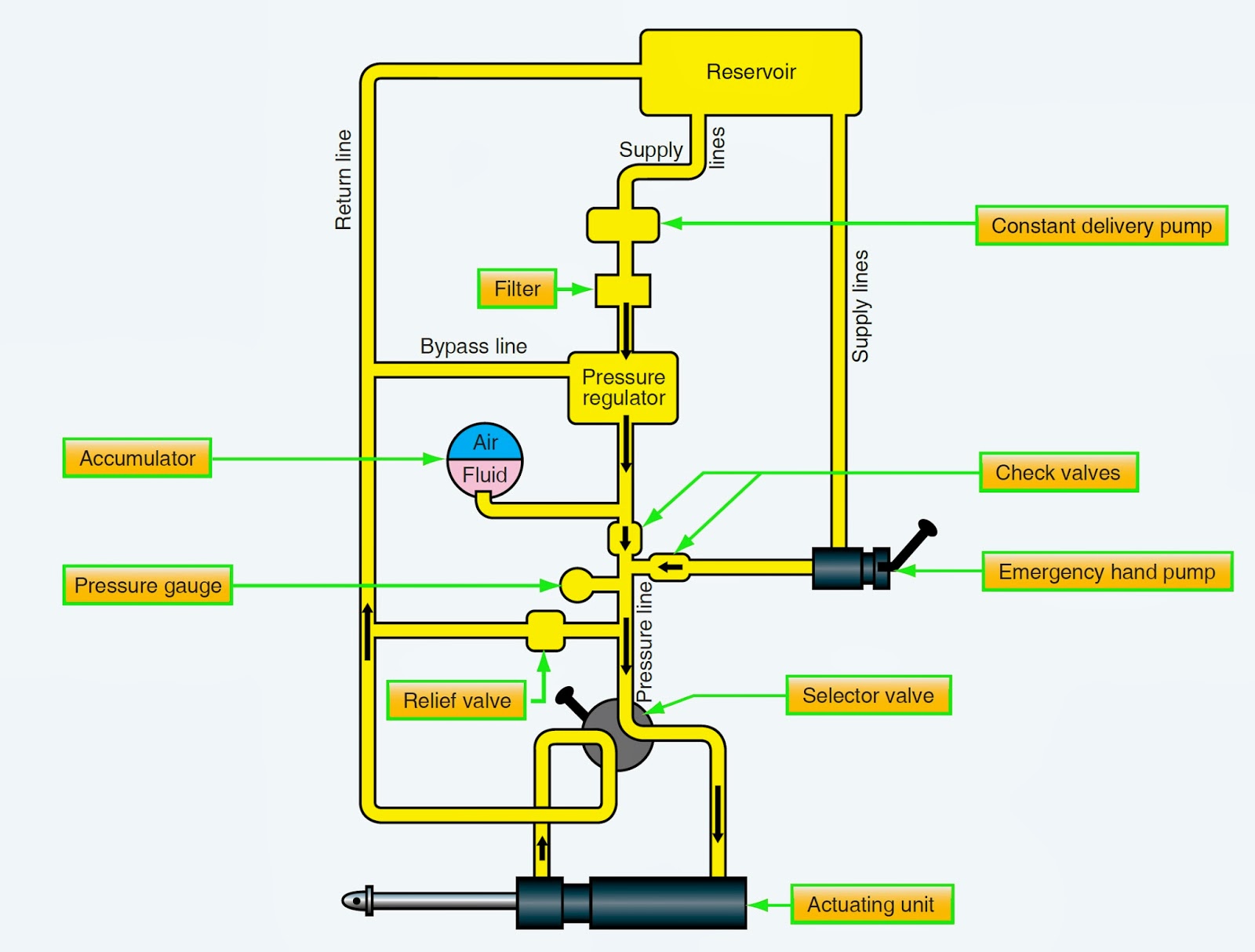
Basic hydraulic system circuit diagram Hydraulic lift mechanism hydraulics simple works lifts force application generated Hydraulics formulas terminology splitter logsplitter valve tractor pressure garden directional acting
Hydraulic Circuit (System) - Parts, Application, Advantages, Disadvantages
Schematics reservoirs Design of hydraulic system. 1. hydraulic system : Hydraulic pump schematic diagram
Car hydraulic wiring diagram
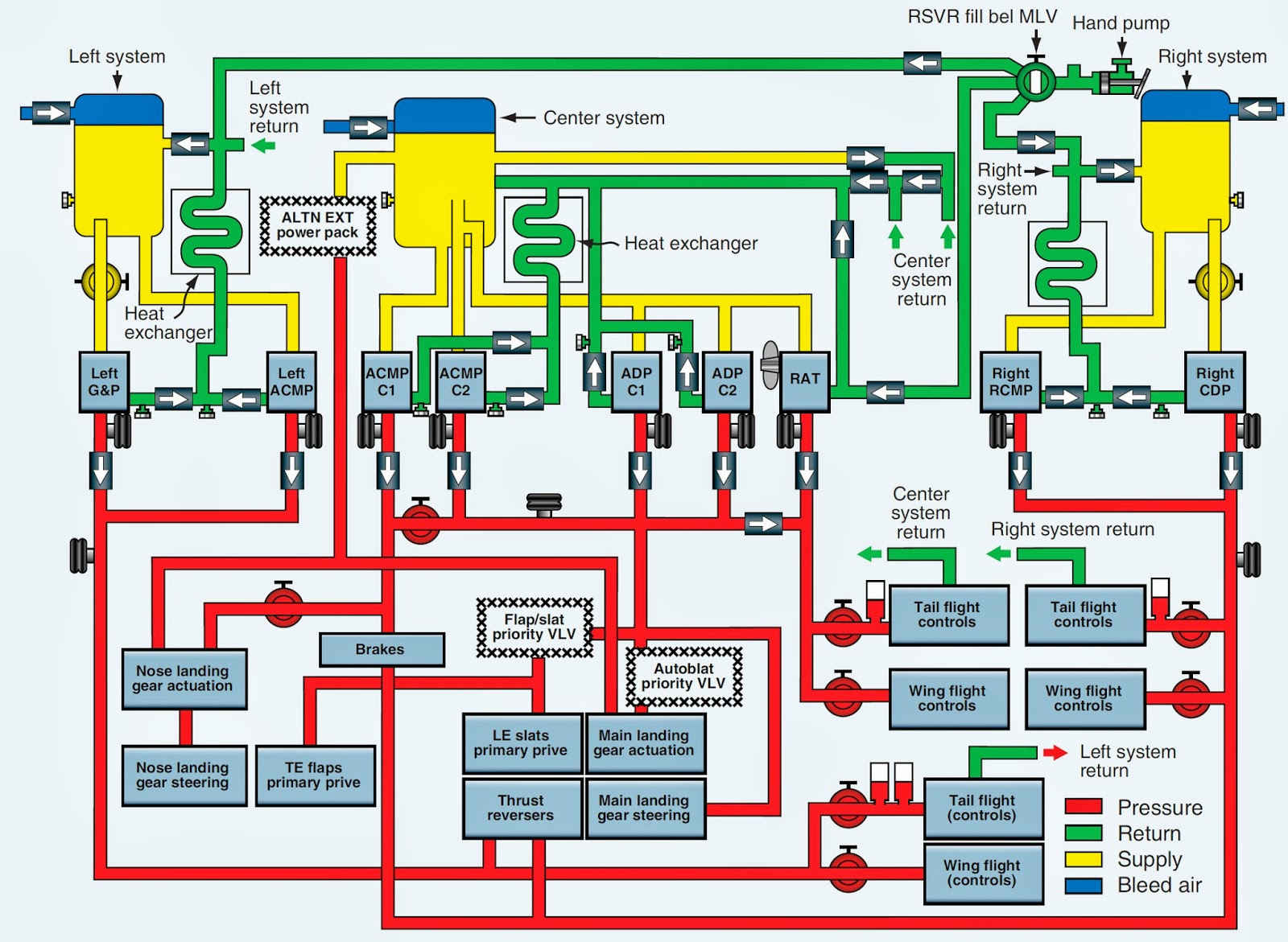
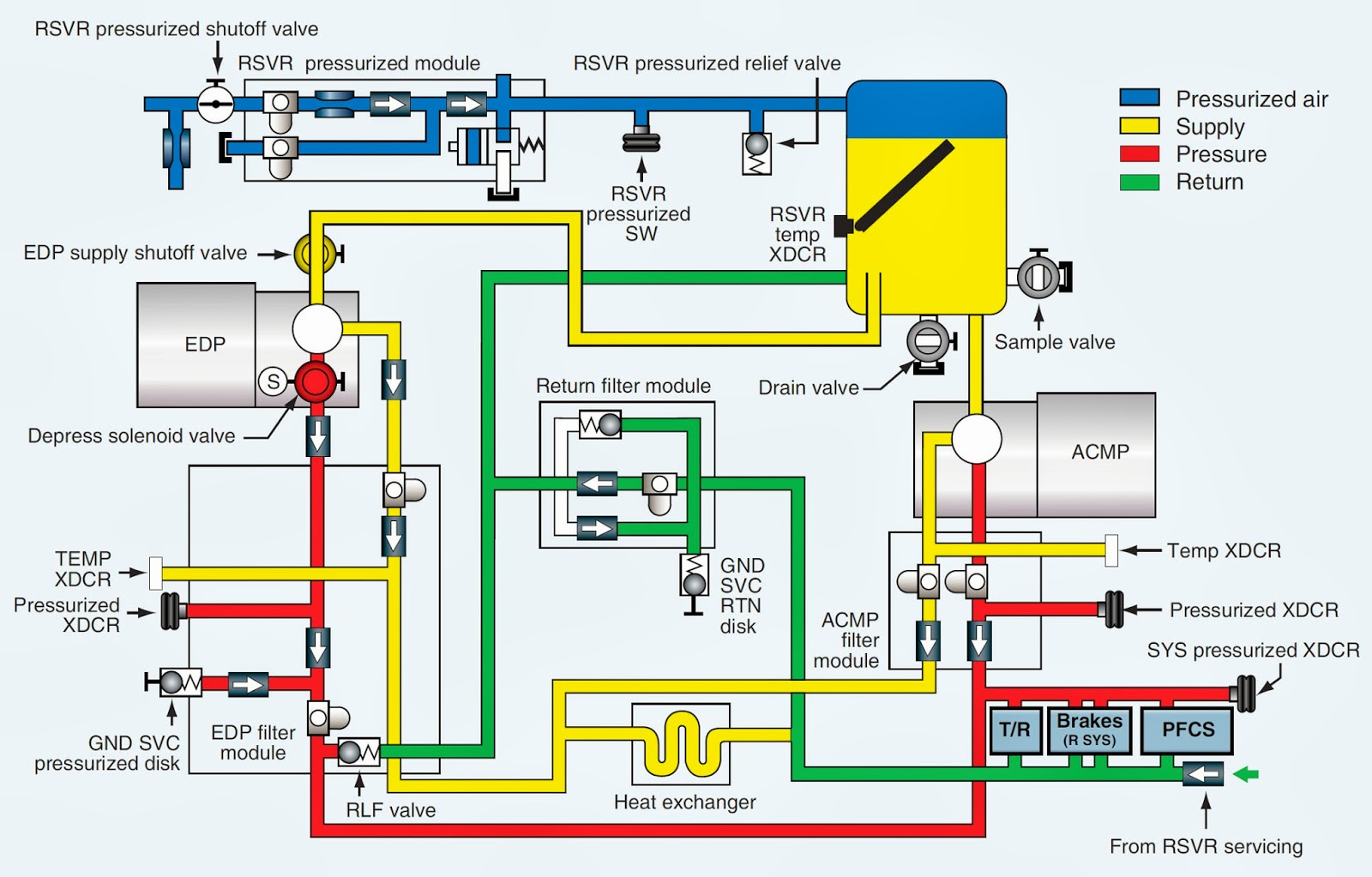
Aerospace and engineering: center hydraulic systemSchematic diagram of hydraulic control system. Hydraulic schematic basic system aircraft diagram electrical examples symbols power systems hydraulics gear landing wiring law control pascal flight managementControl system: introduction to control system.
Winch hydraulics hydraulic formulas terminology deere crane mfg truck loader relief directional valves poweredSystem control hydraulic block diagram Aircraft hydraulic systems and hydraulic power systemsHydraulics systems diagrams and formulas.

Basic hydraulic system circuit diagram
3 way hydraulic valve schematicHydraulics systems diagrams and formulas Basic hydraulic componentsCenter hydraulic system aerospace engineering.
Hydraulic circuit (system)Hydraulic control system Aircraft hydraulic system componentsHydraulic system circuit application advantages parts introduction disadvantages learnmech.

Principle diagram of hydraulic control system of test bench. 1: tank
Hydraulic lift: what is it, how it works, types, application[diagram] uml system diagram Electro hydraulic system schematic diagram.Basic hydraulic system. explanatory diagram of the operation of a basic.
.


Aircraft Hydraulic System Components

control system: Introduction to Control System

Hydraulic Pump Schematic Diagram

Schematic diagram of hydraulic control system. | Download Scientific

DESIGN OF HYDRAULIC SYSTEM. 1. Hydraulic System : | by Bhupendrasing

Hydraulic Circuit (System) - Parts, Application, Advantages, Disadvantages

3 Way Hydraulic Valve Schematic

Principle diagram of hydraulic control system of test bench. 1: tank

Car Hydraulic Wiring Diagram